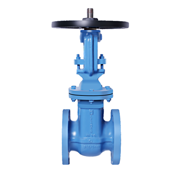
- Item Code: CI0010
- Pressure Rating: PN-1.0
- Testing Standard: As per IS 14846
- Size Range: 50mm to 600mm
- Product Standard: As per IS 14846
Suitable For

Material Specification
| P. NO. | NAME OF PART | MATERIAL |
|---|---|---|
| 1 | KEY | CARBON STEEL |
| 2 | HAND WHEEL RETAINING NUT | CARBON STEEL (IS 2062 Gr. A) |
| 3 | HAND WHEEL | CAST IRON (IS 210 Gr. FG 200) |
| 4 | YOKE SLEEVE RETAINING NUT | LEADED TIN BRONZE (IS 318 Gr. LTB2) |
| 5 | YOKE SLEEVE | LEADED TIN BRONZE (IS 318 Gr. LTB2) |
| 6 | STEM | S.S. (ASTM A276 TYPE 410) |
| 7 | GLAND T-HEAD BOLTS | CARBON STEEL (IS 1363) |
| 8 | GLAND NUTS | CARBON STEEL (IS 1363) |
| 9 | GLAND FLANGE | CAST IRON (IS 210 Gr. FG 200) |
| 10 | GLAND FOLLOWER | LEADED TIN BRONZE (IS 318 Gr. LTB2) |
| 11 | BONNET | CAST IRON (IS 210 Gr. FG 200) |
| 12 | GLAND PACKING | TO SUIT SERVICE CONDITIONS |
| 13 | BACK SEAT BUSHING | LEADED TIN BRONZE (IS 318 Gr. LTB2) |
| 14 | GASKET | C.N.A.F. |
| 15 | BOLTS & NUTS | CARBON STEEL (IS 1363) |
| 16 | BODY | CAST IRON (IS 210 Gr. FG 200) |
| 17 | WEDGE | CAST IRON (IS 210 Gr. FG 200) |
| 18 | WEDGE RING | LEADED TIN BRONZE (IS 318 Gr. LTB2) /S.S.(13% Cr. STEEL) |
| 19 | BODY SEAT RING | LEADED TIN BRONZE (IS 318 Gr. LTB2) /S.S.(13% Cr. STEEL) |
| 20 | GEAR BOX ASSY | ---- |

Dimensional Data

| SIZE (mm) | 50 | 65 | 80 | 100 | 125 | 150 | 200 | 250 | 300 | 350 | 400 | 450 | 500 | 550 | 600 | |
|---|---|---|---|---|---|---|---|---|---|---|---|---|---|---|---|---|
| L | 178±1.6 | 190±1.6 | 203±1.6 | 229±1.6 | 254±1.6 | 267±1.6 | 292±1.6 | 330±1.6 | 356±1.6 | 381±3 | 406±3 | 432±3 | 457±3 | 508±3 | 508±3 | |
| T | 16 | 16 | 21 | 22 | 22.5 | 23 | 24.5 | 26 | 27.5 | 29 | 30 | 31.5 | 33 | 46.5 | 36 | |
| ∅b | 50 | 65 | 80 | 100 | 125 | 150 | 200 | 250 | 300 | 339 | 387 | 440 | 489 | 550 | 591 | |
| ∅D | 165 | 185 | 200 | 220 | 250 | 285 | 340 | 395 | 445 | 505 | 565 | 615 | 670 | 750 | 780 | |
| ~H | 365 | 447 | 490 | 496 | 571 | 647 | 831 | 963 | 1105 | 1175 | 1450 | 1614 | - | - | - | |
| ~H1 | - | - | - | - | - | - | - | - | - | - | - | - | 2513 | 2762 | 2767 | |
| ~∅HW±5 | PN 1.0 | 225 | 225 | 225 | 320 | 320 | 320 | 360 | 400 | 600 | 560 | 450 | 750 | 450 | 450 | 450 |
| K | 125 | 145 | 160 | 180 | 210 | 240 | 295 | 350 | 400 | 460 | 513 | 565 | 620 | 692.2 | 725 | |
| n | 4 | 4 | 4 | 8 | 8 | 8 | 8 | 12 | 12 | 16 | 16 | 20 | 20 | 20 | 20 | |
| ∅d | 19 | 19 | 19 | 19 | 19 | 23 | 23 | 23 | 23 | 23 | 28 | 28 | 28 | 35 | 31 | |
Principle Features
INTRODUCTION
Leader Cast Iron Sluice Valves (Rising Spindle) are best suited for services that require infrequent valve operation, and where the wedge is kept either fully opened or fully closed. It offers the ultimate in dependable service wherever minimum pressure drop is important. Outside screw and yoke (OS&Y) feature offers quick visual indicator of open/closed position is required. The OS&Y configuration protects the stem.
- Design Std.:As per IS:14846.
- Bolted Bonnet, outside screw & Yoke type, Rising Stem.
- Solid Wedge, Metal to Metal seating.
- Gun Metal Body & Wedge rings, Stainless Steel Stem.
- Flanged ends as per IS:1538 (FF).
- Compact & rigid structure.
- Provided full flow with minimal pressure drop.
- Small opening and closing torque.
- The outside screw & Yoke configuration protects the stem & offer quick visual indicator of open/closed position.
- Using Non-Asbestos packing, reliable sealing, light and flexible Operation.
- Robust construction of hand wheel in open spoke design.
- Provision for re-packing under pressure in the installed condition.
- Easy visual control of open/closed position marked on the hand wheel.
- Operation mode manual, gear, electric, pneumatic.
- Available with open-shut indicator & locking arrangement on request.
- Widely applied for low-pressure and ambient-temperature utility services such as water supply, power plants, sewage treatment, gas supply, district heating piping, irrigation projects, air conditioning systems, as well as food processing industry, chemical and petrochemical industry, pharmaceutical and powder industry for access or cut off the medium pipeline opening and closing devices.
END CONNECTION
- Flanged as per IS:1538 F.F.
- Flange drilling as per other standards also available upon request.
UTILISATION & SERVICE
- “LEADER” Cast Iron Sluice valves are suitable for above-ground installations.
- Best suited for potable water, treated fresh water, neutral liquids & some gases.
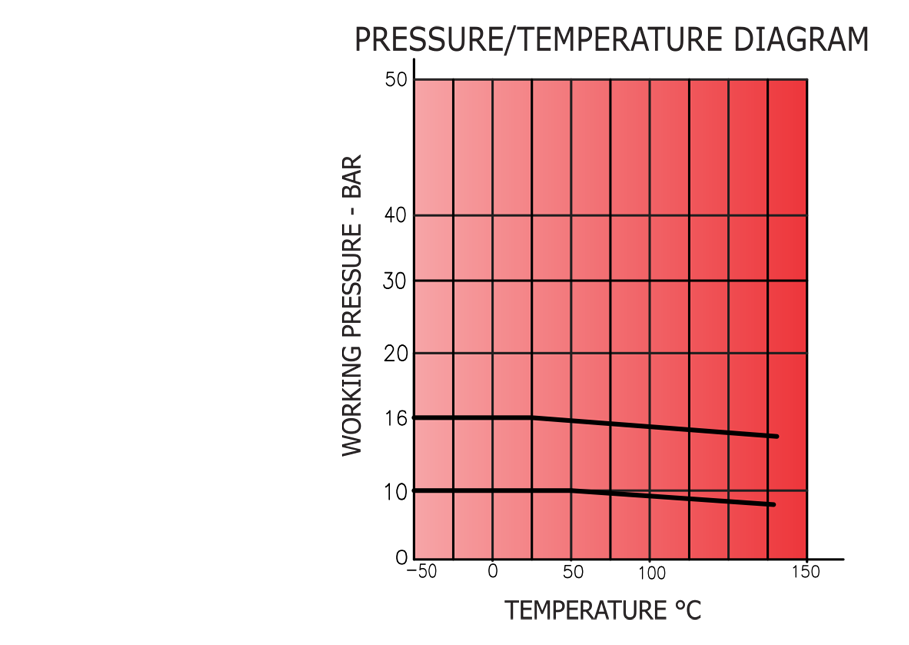
WORKING PRESSURE
- Maximum Working Pressure: (PN 1.0) 10 Bar.
- See Pressure / Temperature Diagram.
TEMPERATURE LIMITS
- Maximum Working Temperature: 220°C.
- See Pressure / Temperature Diagram.
TEST PRESSURE (Hydrostatic)
| Rating | PN-1.0 |
|---|---|
| Body (Hyd.) | 1.5 MPa |
| Seat (Hyd.) | 1.0 MPa |